Adding a linear amp to the Ham Shack
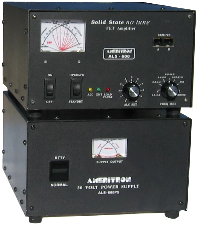
A buddy of mine, who winters in Florida every year, made the generous offer to lend me his 600 watt Ameritron ALS-600 solid state linear amplifier and an LDG AT-600 Pro II tuner while he is away for five months.

Since I haven't had a linear amp in my shack before, there were a number of considerations:
- Power: the amp requires either 12 amps @ 120VAC or 6 amps @240VAC. Since my entire shack had been running via an extension cord plugged into a single outlet, it became obvious that some improvements would need to be made. Another potential issue was amp's power supply, which was wired for 120VAC.
- Feed line and antenna: ensure that my antenna system is capable of handling 600 watts
- Interfaces: I needed to ensure that I had the correct cabling to interface my ICOM IC-7300 to the amp as well as the tuner.
- Modes and operating: I run a lot of digital (FT8/FT4/etc) and I needed to research the amp to learn what it's capable of from a duty cycle vs power perspective.
1. Power
Before I get started here, please understand that what is described below should be done by a qualified electrician, according to local electrical codes. I am not a qualified electrician, nor am I 100% certain that what I describe below is up to code. I do know, from 40+ years of working with electrical circuits, that what I did is completely safe, but any time you mess around with high voltage/current, be very careful and hire an expert if you have any trepidation about it whatsoever. If you decide to undertake a project like this yourself, you do so at your own risk. My lawyer thanks you. :-)
The first order of business was addressing the power situation. Since it was immediately obvious that there was no way I could run 12 amps across my existing 120VAC connection, I started thinking about running 240VAC into the shack. This turned out to be surprisingly easy, for two reasons: 1) I have an unused 240V circuit intended for an electric dryer (we have gas), and 2) since my shack is located in our unfinished basement, it turns out that the 240V cable runs pretty much right over the shack!
I went into this with a little trepidation, as while I've done a ton of 120V wiring around the house, I'd never really used a 240V connection, much less wired one. And as I found out, unlike 120V outlets, there is a dizzying array of 240V outlet/plug combinations, due to the wide variety of applications that demand varying degrees of protection and amperage capacity. The dryer outlet, for example, is comprised of three connections (note: many newer homes will have 4 connections): hot 1, hot 2, and neutral. As it turns out, in North America, the two "hot" wires each carry 120VAC, running in opposite phases. The neutral wire allows the appliance to also run a 120VAC circuit, which is commonly used to run the electronics/lights/etc.
The next step was then to ensure that I had identified the correct 240V cable and then verifying which circuit breaker controls it. Since it's an existing circuit that terminates behind my dryer, I thought it would be as simple as just putting my meter's leads into the outlet, to verify that it's live, and then I could figure out the circuit breaker from there. Well....it wasn't quite that easy. The dryer outlet's conductors are actually really far back into the "holes," and my meter's probes wouldn't reach. So, I was off to the hardware store to buy a dryer cord with the proper connections.
With the new dryer cord, I was quickly able to verify that that two hot wires were delivering a very tidy 240VAC, and by measuring between each hot and the neutral pole, I got 120VAC on each. I then made a trip out to the circuit breaker, found the obvious switch (it was the only dual pole 40 amp circuit in the box), turned it off, and verified that power was 0V at the outlet. So far, so good.
My next challenge was to figure out what connector to choose for the 240V circuit. After doing some research, I discovered that a lot of the linear amps, if provisioned for 240V, use the NEMA 6-20P plug, which is designed to handle 20 amps @ 240VAC. It looks like this:

Note that the plug looks a lot like the standard 120V plug, except one of the "blades" is turned 90 degrees so that you can't plug a 120V plug into it. So I purchased both a plug and an outlet, since the Ameritron was configured for 120V originally. More on that later. I also picked up 50 feet of 12 gauge, 4 conductor "Romex" wire as I would need to tap into the existing 240V cable, install a junction box, and run the line over to the shack. Naturally I also picked up a couple of outlet boxes and a junction box. I nearly passed out when I saw the cost of the cable: $75! Copper has certainly gotten expensive.
While I was thinking all of this through, it also occurred to me, given that this circuit is capable of delivering 40 amps, I could also add in a couple of 120V outlets, wiring each into one of the hot sides of the 240V feed. So, I would go from a single extension cord with sketchy current limits to one 240V and two 120V outlets, capable of delivering a total of 40 amps to the shack, all via a single cable run. NOTE: I'm not 100% sure how this works in relation to the electrical code, so don't take this as a best practice. I can verify that it worked well for me.
Once I had acquired all of the parts needed, I double-checked that the circuit breaker was off, located the place where I wanted to install the junction box, put on my lineman's gloves, safety glasses, etc., and cut the existing 240V line. I then stripped both sides of the cut line, put them into the junction box, ran the new 4-wire cable into the box, and connected the lines with wire nuts. NOTE: since I live in an older home, the existing 240V line did not include a ground wire. So, in keeping with code and best practices, I ran a separate ground wire from the point where the house ground connects to the internal plumbing (which, conveniently, was only about 5 feet from my j-box) and connected it to the new 4-wire cable's ground wire.
Then, I ran the cable over to the shack, drilling holes in the floor joists for the cable run, and then wired up the new outlets.

The existing 240V supply line, just after cutting it in two. Note the house ground (green) just above it.

View of the new junction box with the two hot wires, neutral and new ground wire connected together.

View of the new 120V outlet. Note that I broke the connection between the upper and lower outlets and connected each of the 240V "hot" wires to the two 120V outlets, giving me two separate 120V, 20 amp circuits to draw from. Neutral from the 240V line (white) and the ground are connected on the other side.

The new 6-20P 240VAC outlet. Unfortunately I forgot to snap a picture of the actual wiring, but was pretty simple: each of the 120V "hot' wires went to the upper two connectors, and ground was connected to the ground connector
Changing the Ameritron power supply over to 240VAC
The final challenge was to rewire the Ameritron ALS-600PS power supply for 240 volts. This wound up being the biggest challenge yet. I had naively assumed, based on a quick review of the amp's documentation, that it was a simple jumper change required in the power supply, and of course switching the connector over to the 6-20P. Well....in theory, that was true. Read on....
As it turns out, the power supply changes actually required desoldering/resoldering a couple of jumpers inside the power supply. The hardest part was actually getting to the power supply board in question, as it required the removal of around 25 screws just to get the cover off, then removal of a metal shield and cooling fan. This is what the power supply board originally looked like:


The ALS-600PS jumpers after 240V conversion
After reassembling the unit and retrofitting the power plug to a 6-20P, it was time to try it all out.
Testing
I switched on the breaker and raced downstairs to make sure nothing was on fire. :-) Nothing was. Whew! Next, I broke out the multimeter and checked the voltage at the outlets:


Success! And what a relief! Next step: plug it all in and see if it works!

View of the finished outlets; two 120V circuits on top, 240V on the bottom. The top 120V outlet powers my workbench and the bottom powers my ham shack. Below you can see the ALS-600PS plugged into the new 240V outlet. Note that for the 120V outlet I just ran a short bit of 3-wire Romex between the two boxes to provide the electrical connection as described above.
2. Feedline and antenna
I currently use about 30 feet of RG-8X coax for my feed line from the shack outside, which first terminates in a lightning arrestor (which is grounded via three 8-foot rods, about 6 feet apart), and then I have LMR-400 coax running from there up to the Unun. I was a bit worried about the RG-8/X, as I know that it's not the best quality coax (I have a spool of RG-8/U waiting to be installed when the weather improves). Fortunately, according to multiple sources, RG-8/X can handle 1500 watts @ 10 MHz and 800 watts @ 50 MHz, so that should be fine. And when I get my RG-8/U in place, it will handle 3500/1500 watts (10 MHz/50 MHz respectively). So feedline is not an issue. There is a good article on coax power handling capabilities here.
As for an antenna, for HF, I use a 62-meter "random wire antenna", which runs up at a 15-meter elevation throughout my property in an inverted L configuration. The wire is 13-gauge stranded copper, and I interface it to my radio via a Palomar Engineers 49:1 "bullet" Unun rated for 500 watts. I'm not planning on running the amp much higher than 400 watts, so the antenna shouldn't be a problem. In case you're interested, you can find the specs on my antenna system here.
4. Interfaces
Interfacing the amp to my radio was pretty much a piece of cake. There were two connections required between my IC-7300 and the amp; one is for ALC and the other is for the "Relay" connector. Both use standard RCA shielded cables, which I have about a 100 of, so that wasn't a problem. The other interface, which is technically optional but really convenient, is a control cable between the IC-7300 and the LDG tuner. I found one for $10 at Ham Radio Outlet and it took longer to open the box than it took to install the cable. Once installed, the radio totally controls the tuner, so it's pretty much plug-and-play.
5. Modes / Operating
Once I had all of the physical and electrical issues solved and deployed, it was time to research exactly how to use the amp, and what its limitations are. I was particularly worried about high duty cycle applications like digital modes (FT8/FT4/etc), although in my opinion, running a weak signal mode like FT8 over 600 watts just seems wrong. I feel bad running 100 watts on FT8.
As it turns out, my concerns were well founded. There are a number of articles on eham.net with reports of running high duty cycle digital modes on the ALS-600 blows the finals. So....I definitely won't be using it for that! If you would like to read more reviews on the ALS-600, check them out here.
That said, when running SSB and CW, extra power definitely helps, particularly during contests or nets. For a first test, I setup my IC-7300 to send some 'CQ TEST' transmissions so that I could test how the amp works, and see how far my signal went using the RBN (Reverse Beacon Network). The amp worked great, and RBN showed that my CW signals were being heard all over the place. It was during the day and also during a period of high solar activity, and 10 meters worked great. If you would like to watch a quick video of the amp in operation, check it out here. I also came across a great little article on recommended CW settings for the IC-7300 and the ALS-600 here.
Next, I tried throwing a few CQs out using SSB, but at that point it was getting pretty late in the day and I didn't get any answers. So I decided to try jumping on the OMISS net, which runs a late 80 meter net. The amp worked great. I had 5 QSOs, including a 5/5 signal report from Florida and a 5/9 signal report from Georgia. Success! I can guarantee that I would never have received a 5/5 from Florida before.
Conclusions
To sum things up, this was a great learning experience for me, not only being able to play with an amplifier for the first time, but also in getting over my fears of running 240V circuits. It was fun being able to convert my buddy's amp over to 240V, and I'm really looking forward to seeing what an additional S-unit will do (that's what the increase from 100 watts to 400 watts will buy you). And down the road, deciding on which amp to buy for permanent use.
I hope you enjoy this blog and feel free to drop me a note any time. My contact info can be found on qrz.com.
73s,
Mark K0EHR
Links to equipment referenced or used in this blog:
Amazon Professional multimeter (no longer sold but similar to this Klein meter)

Comments
Post a Comment